Module and Sub-module
The basic unit of description is called a module in SFL. A module represents a component with a definite physical boundary (a component class, to be precise), which constitutes a unit in the hierarchy of the circuitry to be designed. A module can use other modules in its definition; i.e., a module can be defined hierarchically. For a module to be defined hierarchically, the interfaces of the lower-level modules must be declared in advance. The content of the lower-level modules is defined separately. For instance, module "A" using module "B" is defined as follows:
declare B {.... }		;Declaration of module "B"

module  A {.... B .... }	;Definition of module "A" using module "B"

module  B {.... }		;Definition of module "B"
In SFL, "declare" is the key word for declaring a module interface, and "module" is the key word for defining a module.
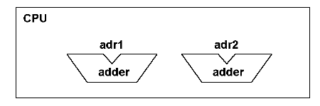
<Fig 3.1> Module and sub-module

In a hierarchical representation, each of the lower-level modules (or instances) is called a sub-module. For example, in the case of Figure 3.1, the CPU (class name) module consists of two sub-modules, namely adder (class name) modules. The names of the sub-modules are adr1 and adr2 (instance names).
The Functional Circuit
The kinds of modules that are not subject to logic synthesis are called functional circuits. A functional circuit is used when an existing circuit whose internal structure (the netlist or mask pattern) is already defined elsewhere is to be used as a module.
A functional circuit is defined by the key word "circuit".
circuit B {.... } ;Definition of functional circuit "B"